
TM 5-3825-270-23&P
0084
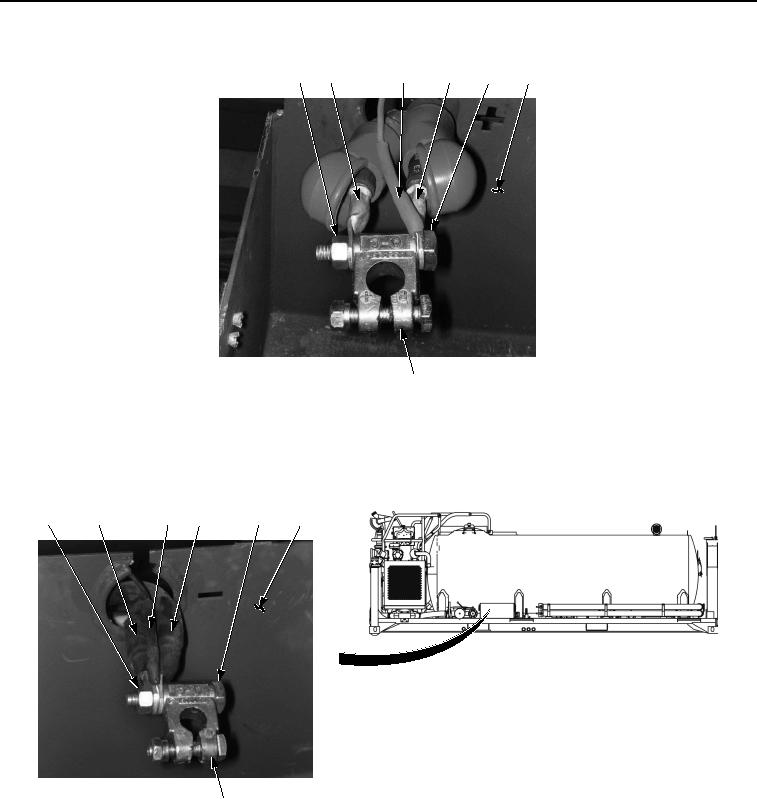
INSTALLATION - Continued
17
18
19
20
21
15
22
Figure 13. Battery Box Wiring Installation.
9.
Install negative battery cable (Figure 14, Item 13), black wire (Figure 14, Item 12), and negative battery cable
(Figure 14, Item 11) in battery box (Figure 14, Item 15) and on terminal (Figure 14, Item 16) with screw (Figure
14, Item 14) and nut (Figure 14, Item 10).
10
11
12
13
14
15
16
Figure 14. Battery Box Wiring Installation.
10.
Install negative battery cable (Figure 15, Item 9) and black wire (Figure 15, Item 8) on starter (Figure 15, Item
6) with nut (Figure 15, Item 7).