
TM 5-3825-270-23&P
0084
INSTALLATION - Continued
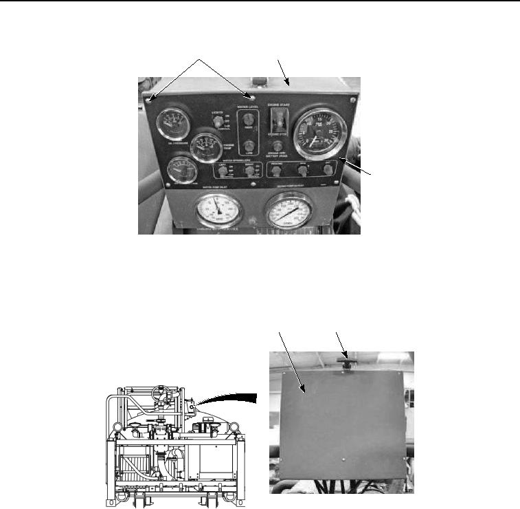
25, 26
27
28
Figure 11. Battery Box Wiring Installation.
6.
Install six washers (Figure 7, Item 26) and screws (Figure 7, Item 25) on main control box (Figure 7, Item 27)
and control panel (Figure 7, Item 28). Tighten six screws securely.
7.
Close control box cover (Figure 12, Item 23) and secure with rubber t-handle (Figure 12, Item 24).
23
24
Figure 12. Battery Box Wiring Installation.
8.
Install positive battery cable (Figure 13, Item 20), clear wire (Figure 13, Item 19), and positive battery cable
(Figure 13, Item 18) in battery box (Figure 13, Item 15) and on terminal (Figure 13, Item 22) with screw (Figure
13, Item 21) and nut (Figure 13, Item 17).