
TM 5-3825-270-23&P
0067
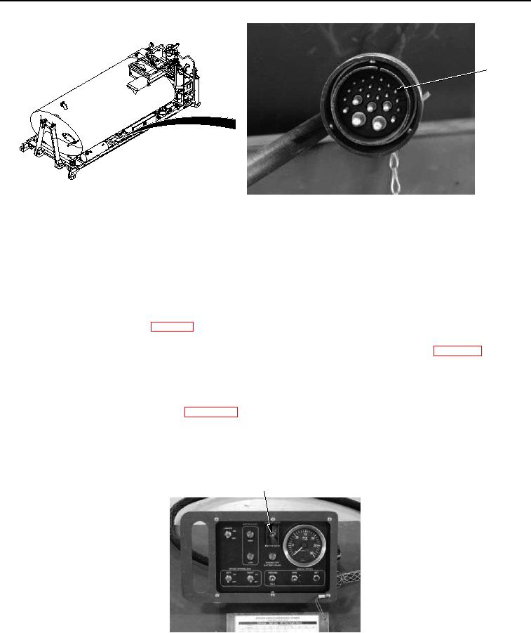
PIN F
Figure 10. UPIK Harness Connector Pin F - Step 7.
4.
Connect black multimeter lead to a known good ground.
5.
Note multimeter reading.
CONDITION/INDICATION
Are less than 200 ohms measured at UPIK harness connector pin F to known good ground?
DECISION
No - Replace UPIK harness. (WP 0108) Verify problem is solved. (Step 8 - Does cab control box ENGINE START/
STOP switch operate?)
Yes - Wiring in cab control box harness is faulty. Replace cab control box wiring harness. (WP 0206) Verify
problem is solved. (Step 8 - Does cab control box ENGINE START/STOP switch operate?)
STEP 8
Does cab control box ENGINE START/STOP switch operate?
1.
If disconnected, connect batteries. (WP 0085)
2.
Ensure water distributor is set up to be operated using cab control box. (TM 5-3825-270-10)
3.
Rotate EMERGENCY STOP switch to on position. (TM 5-3825-270-10)
4.
Operate engine using cab control box ENGINE START/STOP switch.
CAB CONTROL BOX ENGINE
START/STOP SWITCH
Figure 11. Cab Control Box Engine Start/Stop Switch - Step 8.
CONDITION/INDICATION
Does cab control box ENGINE START/STOP switch operate?