
TM 5-3825-270-23&P
0065
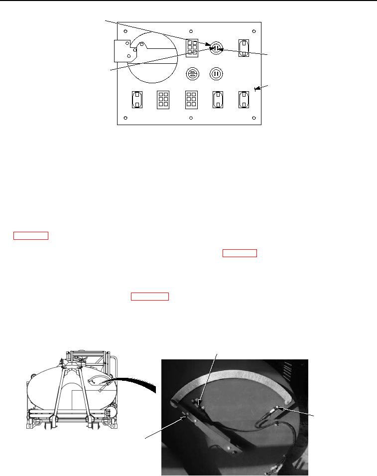
CAB CONTROL
BOX WATER
LEVEL HIGH
INDICATOR
BLACK JUMPER
WIRE
BLACK WIRE
BACK OF CAB
CONTROL BOX
Figure 10. Cab Control Box Water Level High Indicator - Step 6.
2.
Connect black multimeter lead to black wire at WATER LEVEL LOW indicator.
3.
Note multimeter reading.
CONDITION/INDICATION
Are less than 200 ohms measured from black wire at WATER LEVEL HIGH indicator to black wire at WATER
LEVEL LOW indicator?
DECISION
No - Replace black wire between WATER LEVEL HIGH indicator and WATER LEVEL LOW indicator.
(WP 0099) Verify problem is solved. (Step 7 - Does cab control box WATER LEVEL HIGH indicator
illuminate?)
Yes - Replace cab control box WATER LEVEL HIGH indicator. (WP 0214) Verify problem is solved. (Step 7 -
Does cab control box WATER LEVEL HIGH indicator illuminate?)
STEP 7
Does cab control box WATER LEVEL HIGH indicator illuminate?
1.
If disconnected, connect batteries. (WP 0085)
2.
Ensure water distributor is set up to be operated using cab control box. (TM 5-3825-270-10)
3.
Rotate EMERGENCY STOP switch to on position. (TM 5-3825-270-10)
4.
With the aid of an assistant, move water level indicator magnet directly over high tank level switch.
LOW TANK
LEVEL SWITCH
HIGH TANK
LEVEL
SWITCH
WATER LEVEL
INDICATOR
AND MAGNET
Figure 11. Water Level Indicator And Magnet - Step 7.