
TM 5-3825-270-23&P
0066
WARNING
Remove all jewelry such as rings, ID tags, bracelets, etc., prior to working on or around
vehicle. Jewelry and tools can catch on equipment, contact positive electrical circuits, and
cause a direct short, severe burns, or electrical shock. Failure to comply may result in injury
or death to personnel.
4.
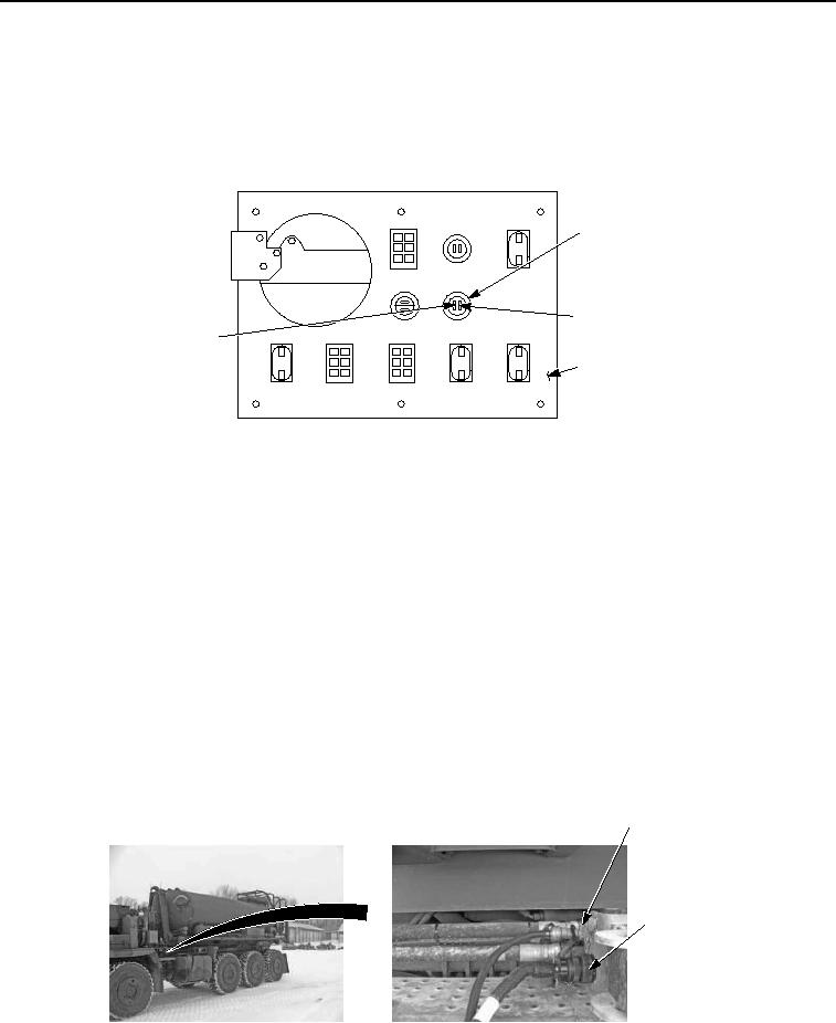
Connect red multimeter lead to white wire on cab control box WATER LEVEL LOW indicator.
CAB CONTROL BOX
WATER LEVEL
LOW INDICATOR
BLACK WIRE
WHITE WIRE
BACK OF CAB
CONTROL BOX
Figure 6. Cab Control Box Water Level Low Indicator - Step 3.
5.
Connect black multimeter lead to a known good ground.
6.
Note multimeter reading.
CONDITION/INDICATION
Are 22 to 28 VDC measured at white wire on WATER LEVEL LOW indicator?
DECISION
No - Go to step 4. (Step 4 - Are 22 to 28 VDC measured at UPIK harness connector pin L?)
Yes - Go to step 5. (Step 5 - Are less than 200 ohms measured from black wire at WATER LEVEL LOW indicator
to black wire at cab control box tachometer?)
STEP 4
Are 22 to 28 VDC measured at UPIK harness connector pin L?
1.
Push EMERGENCY STOP switch in to off position. (TM 5-3825-270-10)
2.
Disconnect water distributor UPIK electrical harness from prime mover.
UPIK AIR
CONNECTION
UPIK
ELECTRICAL
CONNECTION
Figure 7. UPIK Electrical Connection - Step 4.
3.
Rotate EMERGENCY STOP switch to on position. (TM 5-3825-270-10)