
TM 5-3825-270-23&P
0066
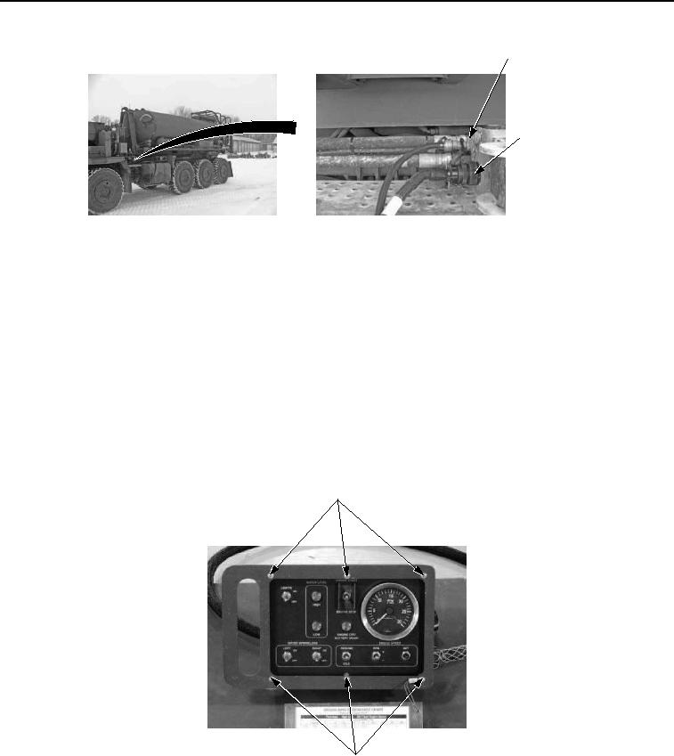
UPIK AIR
CONNECTION
UPIK
ELECTRICAL
CONNECTION
Figure 4. UPIK Air And Electrical Connections - Step 2.
CONDITION/INDICATION
Are cab control box and water distributor harnesses connected properly to prime mover?
DECISION
No - Properly connect cab control box and/or harness connections to prime mover. (TM 5-3825-270-10) Verify
problem is solved. (Step 6 - Does cab control box WATER LEVEL LOW indicator illuminate?)
Yes - Go to step 3. (Step 3 - Are 22 to 28 VDC measured at white wire on WATER LEVEL LOW indicator?)
STEP 3
Are 22 to 28 VDC measured at white wire on WATER LEVEL LOW indicator?
1.
Remove six screws from cab control box.
CAB CONTROL
BOX SCREWS
CAB CONTROL
BOX SCREWS
Figure 5. Cab Control Box Screws - Step 3.
2.
Rotate EMERGENCY STOP switch to on position. (TM 5-3825-270-10)
3.
Ensure multimeter is set to measure voltage.