
TM 5-3825-270-23&P
0025
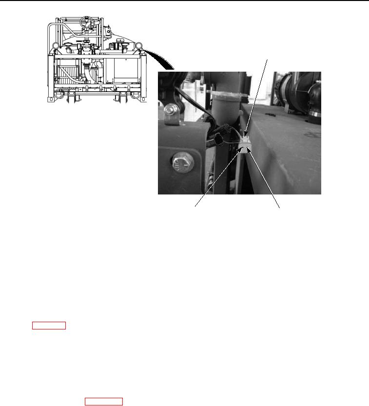
WORK LIGHT
HARNESS CONNECTOR
PIN 1
PIN 2
(RED WIRE)
(BLACK WIRE)
Figure 4. Work Light Harness Connector Pin 2 - Step 4.
5.
Place black multimeter probe to know good ground.
6.
Note multimeter reading.
CONDITION/INDICATION
Are less than 200 ohms measured at work light harness connector pin 2 to known good ground?
DECISION
No - Repair or replace black wire from work light harness connector pin 2 to control panel negative terminal
strip. (WP 0099) Verify problem is solved. (Step 7 - Do work lights illuminate?)
Yes - Problem not found and may have been missed or overlooked. Repeat all previous steps in this
troubleshooting procedure. Go to step 1. (Step 1 - Are both work lights inoperative, or just one?) If problem still
exists after all troubleshooting test have been accomplished, notify supervisor.
STEP 5
Are less than 200 ohms measured across LIGHTS switch terminal 1 and terminal 2 with switch in ON
position?
1.
Push in EMERGENCY STOP switch to off position. (TM 5-3825-270-10)
2.
Disconnect batteries. (WP 0085)
3.
Remove six control panel faceplate screws.