
TM 5-3825-270-23&P
0011
AIR
VENT
COCK
Figure 3. Air Vent Cock (Close) - Step 2.
11.
Operate engine while observing engine performance. (TM 5-3825-270-10)
CONDITION/INDICATION
Is engine operation normal after bleeding fuel system?
DECISION
No - Go to step 3. (Step 3 - Are fuel system components free from leaks and damage?)
Yes - Problem solved.
STEP 3
Are fuel system components free from leaks and damage?
Visually inspect the following fuel system components for damage and leakage. (WP 0069)
Fuel lines and fittings
Fuel pump, lines, and fittings
Fuel/water separator, lines, and fittings
Engine injector pump, lines, and fittings
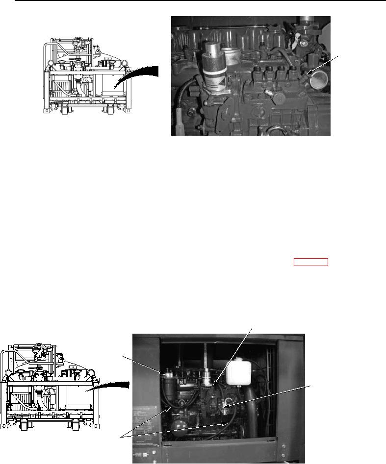
ENGINE INJECTOR
PUMP
FUEL/WATER
SEPARATOR
FUEL
PUMP
FUEL
LINES
Figure 4. Fuel System Components - Step 3.