
TM 5-3820-276-10-1
0053
MUD CLEANING SYSTEM OPERATION - Continued
1
WWDS01013
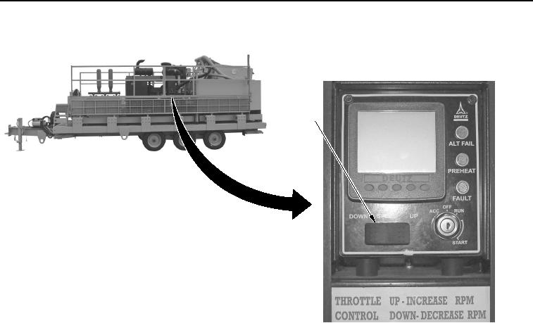
Figure 2.
Engine Speed Switch.
CAUTION
Do not allow the desander pump to run dry. Make sure there is enough water in the tank to
cover the suction of the desander pump. The desander pump is equipped with a
mechanical seal that will overheat. Failure to comply may result in damage to the
equipment.
3.
Ensure valve at bottom of mix hopper (Figure 3, Item 4) is closed.