
TM 5-3820-276-10-1
OPERATOR MAINTENANCE
OPERATING PROCEDURES - GROUTER
INITIAL SETUP:
Personnel Required
Equipment Condition
Two
Grouter setup (WP 0039)
References
STARTING PROCEDURE
1.
Place all valves in closed position (WP 0010).
2.
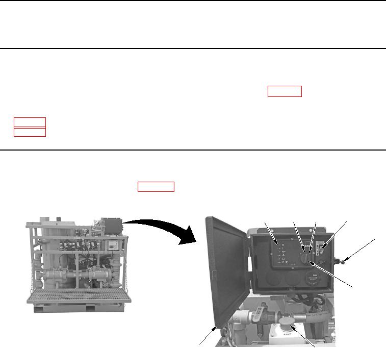
Place EMERGENCY STOP button in up position (Figure 1, Item 7).
3
4
2
1
5
6
8
7
WWDS00420
Figure 1.
Starting Controls.
3.
Release control panel door latch (Figure 1, Item 5) and open door (Figure 1, Item 8).
4.
Set THROTTLE CONTROL switch (Figure 1, Item 4) to OFF position.
5.
Rotate ignition switch (Figure 1, Item 6) to On (I) position (Figure 1, Item 2), and wait until pre-heat indicator
(Figure 1, Item 1) goes out.
6.
Rotate ignition switch (Figure 1, Item 6) to Start (II) position (Figure 1, Item 3).
7.
Release ignition switch (Figure 1, Item 6) to On (I) position (Figure 1, Item 2) when engine starts.
8.
Observe control panel for warning lights.
END OF TASK