
TM 5-3820-276-10-1
OPERATOR MAINTENANCE
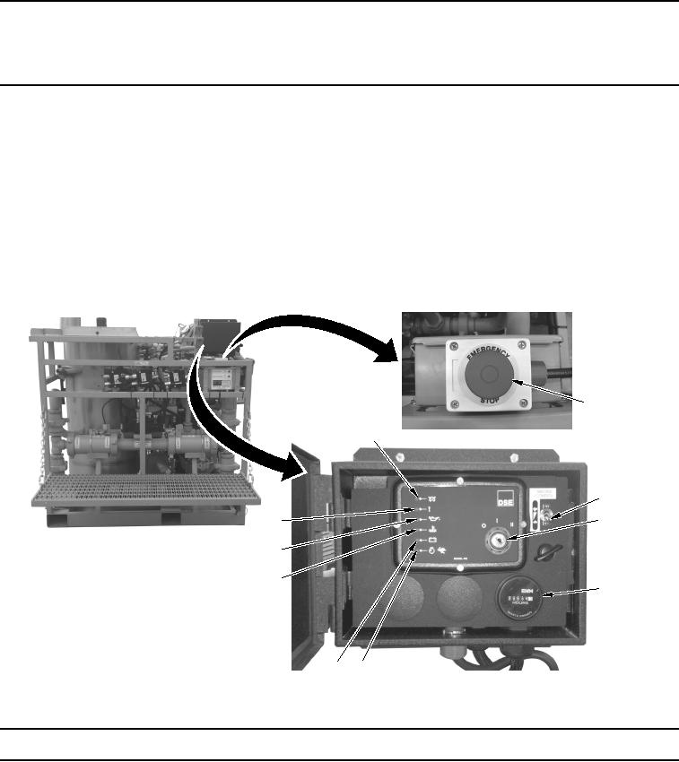
DESCRIPTION AND USE OF CONTROLS AND INDICATORS - GROUTER
INTRODUCTION
This section provides features and functions of the grouter control panel.
NOTE
Before attempting to operate the grouter, be familiar with the location and function of all
controls and indicators.
Tables and illustrations that follow provide description and use of grouter control panels.
Table 1.
Engine Controls and Indicators.
2
1
3
4
10
9
8
5
6
7
WWDS00356
Figure 1.
Engine Controls and Indicators.
Key
Control/Indicator
Function
1.
Pre-heat Indicator
Illuminates yellow when pre-heat is in operation.
2.
EMERGENCY
Used to shut engine down in event of an emergency.
STOP