
TM 5-3820-276-10-1
OPERATOR MAINTENANCE
DESCRIPTION AND USE OF CONTROLS AND INDICATORS - PORTABLE AIR COMPRESSOR (PAC)
INTRODUCTION
This section provides features and functions of PAC control panel.
NOTE
Before attempting to operate PAC, be familiar with location and function of all controls and
indicators.
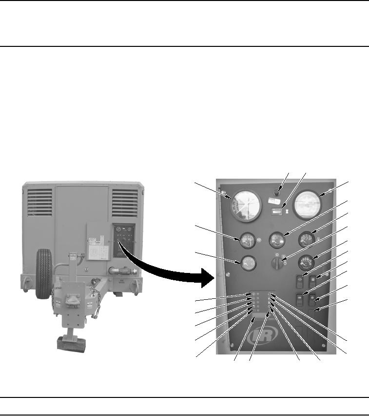
The table and illustration that follow provide description and use of controls and indicators for PAC.
Table 1.
Control Panel Features.
2
3
4
1
5
6
26
7
8
9
25
10
11
12
13
24
23
22
21
14
15
20
19
18
17
16
WWDS00358
Figure 1.
Control Panel Features.
Key
Control/Indicator
Function
1.
DISCHARGE AIR
Indicates pressure in receiver tank, normally from 0 psi (0 kPa) to 350 psi
PRESSURE Gauge
(2,413 kPa).
2.
LAMP
Illuminates instruments and control panel.