
TM 5-3820-276-10-1
0008
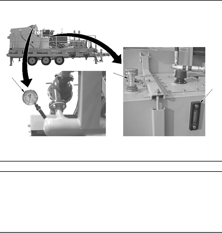
Table 5.
MCS Indicators.
2
1
3
WWDS00158
Figure 5.
Indicators.
Key
Control/Indicator
Function
1.
Desander Cones
Displays the pressure of the desander cones.
Pressure Gauge
2.
Fuel Gauge
Displays the quantity of fuel in the fuel tank.
3.
Hydraulic Oil
Displays the quantity of hydraulic oil in the hydraulic reservoir.
Indicator