
TM 5-3820-276-10-1
0008
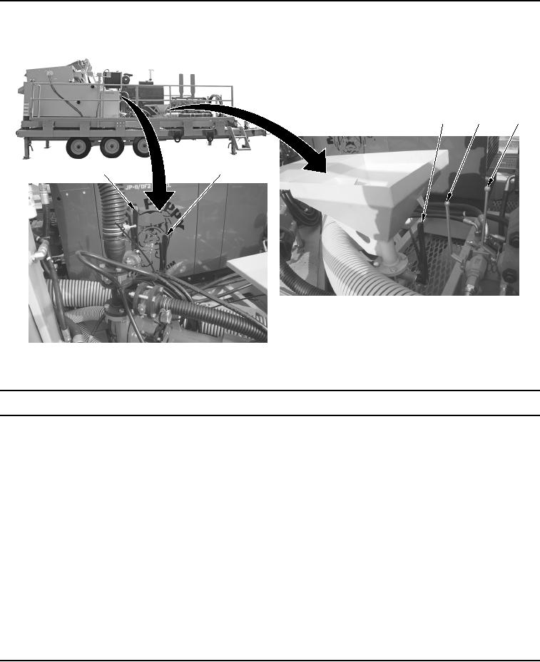
Table 4.
Control Levers.
3
4
5
1
2
WWDS00157
Figure 4.
Control Levers.
Key
Control/Indicator
Function
1.
Desander Pump
Used to control the flow of mud to the desander cones.
Valve
2.
Mud Flow Valve
Used to control the flow of mud through the hopper jet.
3.
Mix Hopper Valve
Used to control the flow of mud product from the mix hopper and into the
mud tank.
4.
Hydraulic Valves
Used to control hydraulic flow to the mud pump.
(Both Valves)
5.
Hydraulic Valves
Used to control hydraulic flow to the mud pump.
(Both Valves)