
TM 5-3820-276-10-1
0008
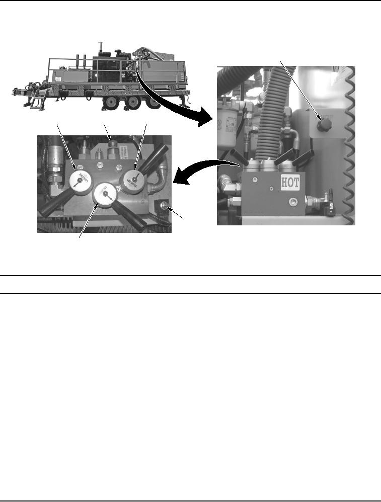
Table 2.
Hydraulic Control Manifold Features.
1
2
3
4
5
6
WWDS00156
Figure 2.
Hydraulic Control Manifold Features.
Key
Control/Indicator
Function
1.
PUMP
Used to control the output of triplex pump.
2.
DESANDER
Used to start or stop the desander pump.
LEVER
3.
ADJUSTABLE
Used by maintenance personnel to adjust hydraulic flow to the sand guzzler.
FLOW CONTROL
Not to be used by operators during normal operations.
4.
SYSTEM RUN/
Used to bypass hydraulic oil during engine start in cold weather. Also used to
ENGINE START
cool overheated hydraulic oil while at idle.
LEVER
5.
APU Manual Over
Used by maintenance personnel to troubleshoot operation of the Auxiliary
Ride Switch
Power Unit (APU). Not to be used by operators during normal operations.
6.
P/U PUMP LEVER
Used to start the sand guzzler and shaker together.