
TM 5-3820-276-10-1
0008
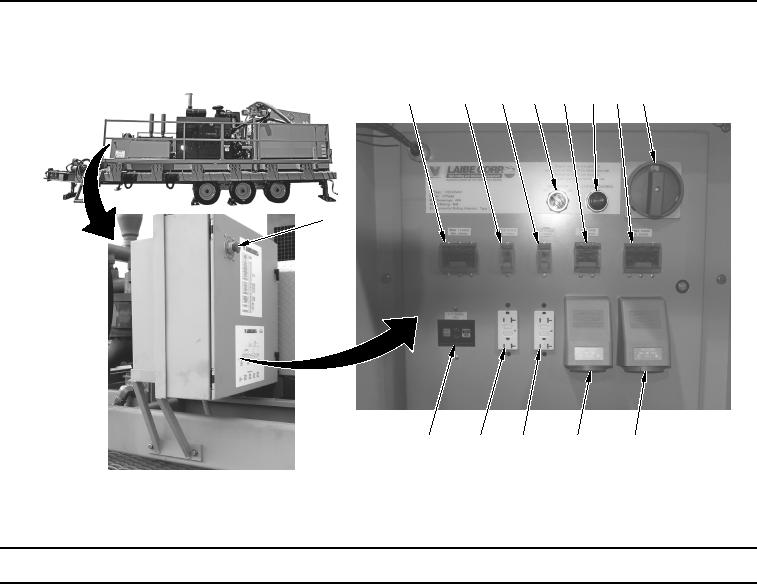
Table 3.
Auxiliary Power Unit (APU) Control Panel Features.
2
3
4
5
6
7
8
9
1
14
13
12
11
10
WWDS00083
Figure 3.
Auxiliary Power Unit (APU) Control Panel Features.
Key
Control/Indicator
Function
1.
EMERGENCY
Used to disconnect the APU power output to the panel.
STOP
2.
MAIN 3 PHASE
Used as a safety device to interrupt main power on the control panel.
40A, 208VAC
3.
SINGLE PHASE
Used as a safety device to interrupt power at the 110VAC outlet on the
20A, 110VAC
control panel.
4.
SINGLE PHASE
Used as a safety device to interrupt power at the 110VAC outlet on the
20A, 110VAC
control panel.
5.
Used to control operation of the APU. Set switch to ON position to pressurize
ON/OFF
the hydraulic circuit and power the APU.