
TM 5-3820-276-10-1
0007
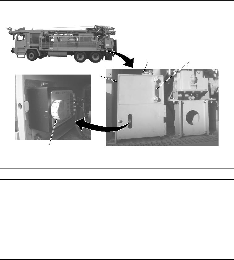
Table 11. Lubricator Assembly - WWDR.
3
2
1
4
WWDS00109
Figure 11. Lubricator Assembly - WWDR.
Key
Control/Indicator
Function
1.
Lubricator
Used to lubricate the Down-Hole-Drill (DHD) during air drilling with a
Assembly
hammer. The lubricator assembly only runs when compressor is running.
2.
Oil Tank
Used to store oil for lubricator.
3.
Sight Gauge
Used as visual indicator of oil level in oil tank.
4.
DHD LUBRICATOR
Used to set the time interval delivery of oil to DHD hammer/air compressor.
TIMER
02/13/2013root(ctrlindwp)wpno(O10002)