
TM 5-3820-276-10-1
0010
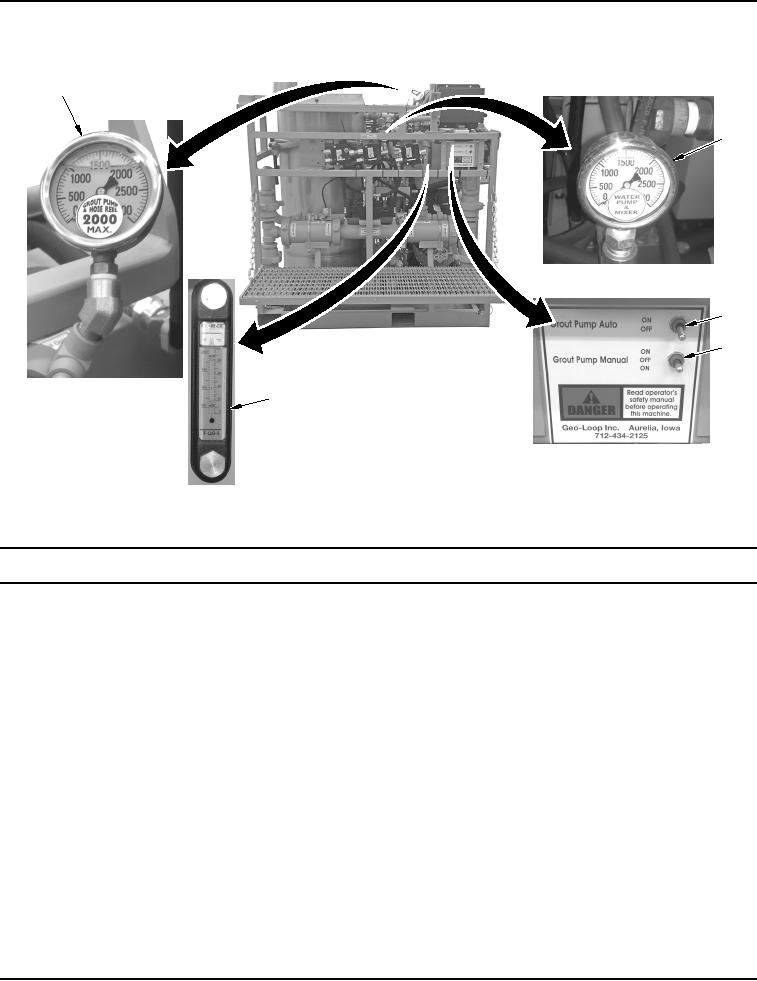
Table 2.
Hydraulic Controls and Indicators.
1
2
3
4
5
WWDS00357
Figure 2.
Hydraulic Controls and Indicators.
Key
Control/Indicator
Function
1.
GROUT PUMP &
Indicates pressure in the hydraulic system.
HOSE REEL
GAUGE
2.
WATER PUMP &
Indicates pressure in the water pump/mixer system.
MIXER Pressure
Gauge
3.
GROUT PUMP
Used with grout pump flow divider to start grout pump flow.
AUTO Switch
4.
GROUT PUMP
Used to bypass micro-switches and relay to manually move pump piston to
MANUAL Switch
far right or left.
5.
Hydraulic Oil Site/
Indicates hydraulic oil level and temperature.
Temp Gauge