
TM 5-3820-276-10-1
0011
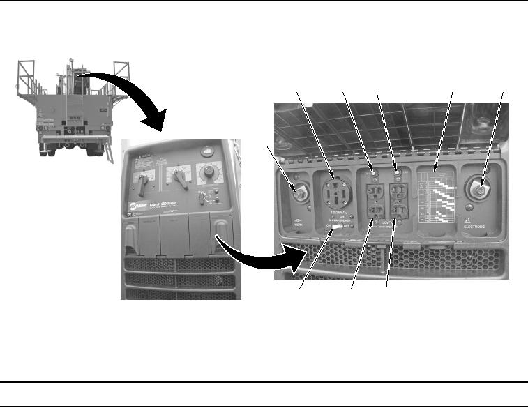
Table 2.
Lower Control Panel.
2
3
4
5
6
1
9
8
7
WWDS00217
Figure 2.
Lower Control Panel.
Key
Control/Indicator
Function
1.
WORK Terminal
Used to connect work clamp cable to welder/generator.
2.
120/240 Volt 50
Used to supply (RC1) 60-Hz single-phase power at weld/power speed.
Amp AC
Receptacle (RC1)
3.
Supplementary
Protects adjoining receptacle (RC2) from overload. If supplementary
Protector (CB2)
protector opens, the receptacle will not work.
4.
Supplementary
Protects adjoining receptacle (RC3) from overload. If supplementary
Protector (CB3)
protector opens, the receptacle will not work.
5.
Amperage Range
Provides information for needed amperage range for various ELECTRODE/
Table