
TM 5-3820-276-10-1
0029
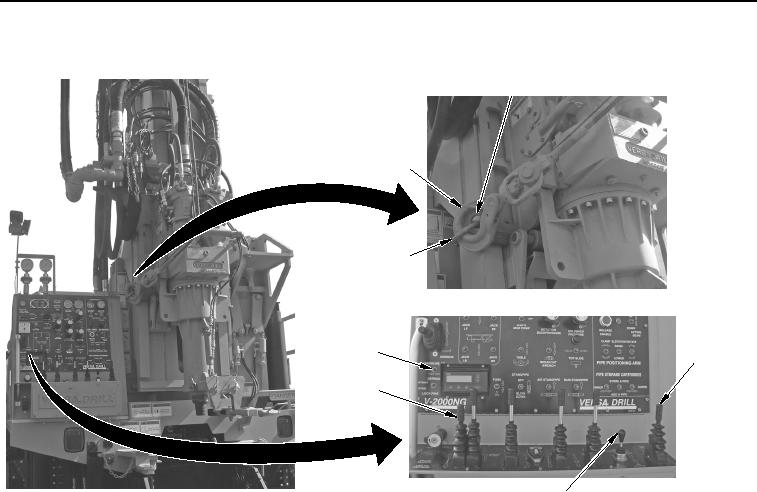
LOWERING DERRICK - Continued
2
1
7
6
3
5
4
WWDS00301
Figure 13. Sandline and Winch Cable Connect.
CAUTION
Ensure cables are in cable guide. Failure to comply may result in damage to equipment.
4.
With aid of assistant, push sandline winch control lever (Figure 13, Item 5) forward to raise sandline cable
and hook (Figure 13, Item 2) enough to connect hook to derrick eyelet (Figure 13, Item 7).
5.
With aid of assistant, push sandline winch control lever (Figure 13, Item 5) forward to raise sandline cable
and hook (Figure 13, Item 2) to remove slack in cable.
6.
With aid of assistant, move JIB ROTATE/JIB RAISE/LOWER control lever (Figure 13, Item 4) left to position
main winch cable inward towards derrick.
7.
Move JIB ROTATE/JIB RAISE/LOWER control lever (Figure 13, Item 4) down to lower jib boom to lowest
position.
CAUTION
Ensure cables are in cable guide. Failure to comply may result in damage to equipment.
8.
With aid of assistant, push main winch control lever (Figure 13, Item 3) up and raise cable and hook
(Figure 13, Item 1) enough to connect hook to derrick eyelet (Figure 13, Item 7).
9.
With aid of assistant, push main winch control lever (Figure 13, Item 3) up and raise cable and hook
(Figure 13, Item 1) to remove slack from cable.
02/13/2013root(opusualwp)wpno(O10014)