
TM 5-3820-276-10-1
0029
RAISING DOWNRIGGERS - Continued
2.
Push down on two rear JACK LR and JACK RR switches (Figure 15, Item 4) to raise two rear downriggers
(Figure 15, Item 6).
3.
Rotate THROTTLE (Figure 15, Item 3) to decrease engine speed on ENGINE RPM gauge
(Figure 15, Item 2) to idle rpm.
4.
Set CONSOLE POWER switch (Figure 15, Item 1) to OFF position.
5.
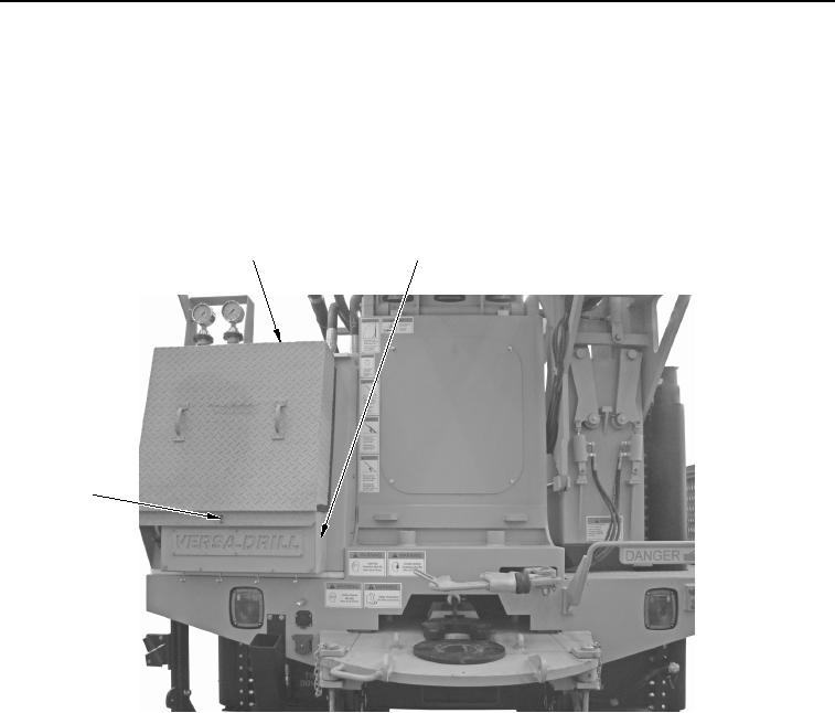
Install console cover panel (Figure 16, Item 1) to drilling console (Figure 16, Item 2).
1
2
3
WWDS00229
Figure 16. Console Cover Panel Installation.
6.
Rotate eyebolt (Figure 16, Item 3) to lock cover panel (Figure 16, Item 1).
END OF TASK
02/13/2013root(opusualwp)wpno(O10014)