
TM 5-3820-276-10-1
0028
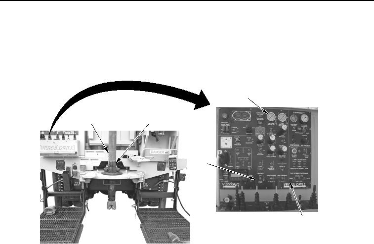
DRILL BIT INSTALLATION - Continued
25.
Pull SLOW FEED control lever (Figure 13, Item 4) back and engage drill bit assembly (Figure 13, Item 2).
3
1
2
5
4
WWDS00676
Figure 13. Drill Rod Attached.
26.
Pull SLOW FEED control lever (Figure 13, Item 4) and ROTATION control lever (Figure 13, Item 5) back
and spin upper drill rod (Figure 13, Item 1) until ROTATION PRESSURE gauge (Figure 13, Item 3) reads
2,100 psi (145 bar).
27.
Set and hold FORK switch (Figure 14, Item 2) to up position to retract fork (Figure 14, Item 1).
02/13/2013root(opusualwp)wpno(O10012)