
TM 5-3820-276-10-1
0028
DRILL BIT REMOVAL
WARNING
Always wear double hearing protection, safety glasses, hard hat, gloves, and steel toe
shoes during operation of the Water Well Drilling System. Failure to comply may result in
injury or death to personnel. Seek medical attention in the event of an injury.
1.
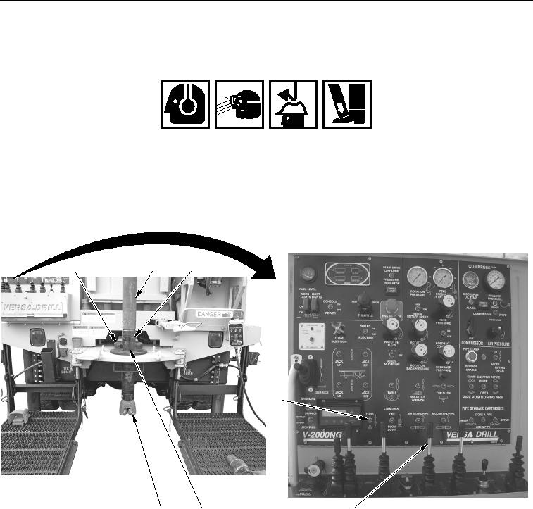
Push FAST FEED control lever (Figure 15, Item 4) forward and raise upper drill rod (Figure 15, Item 2) and
drill bit assembly (Figure 15, Item 3) until tooling joint (Figure 15, Item 6) is approximately 0.5 in. (13 mm)
above top of fork (Figure 15, Item 1).
1
2
3
5
7
6
4
WWDS00938
Figure 15. Drill Bit from Sub Removal.
2.
Set FORK switch (Figure 15, Item 5) to down position to extend fork (Figure 15, Item 1).
3.
With aid of an assistant, remove drill bit (Figure 15, Item 7) from sub (Figure 15, Item 3).
4.
Set BREAKOUT WRENCH switch (Figure 16, Item 4) to down position and attach breakout wrench
(Figure 16, Item 2) to upper drill rod (Figure 16, Item 1).
02/13/2013root(opusualwp)wpno(O10012)