
TM 5-3820-276-10-1
0028
DRILL BIT REMOVAL - Continued
8.
Push FAST FEED control (Figure 17, Item 5) forward to raise upper drill rod (Figure 17, Item 1) up until
threads (Figure 17, Item 3) are approximately 1 in. (25 mm) above base of automated rod handling arm
(Figure 17, Item 2).
9.
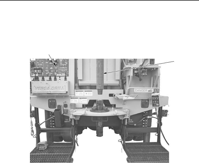
Set TOP SLIDE switch (Figure 18, Item 1) to right position to move drill rod (Figure 18 , Item 2) right.
1
2
WWDS00974
Figure 18. Drill Rod Positioning.
02/13/2013root(opusualwp)wpno(O10012)