
TM 5-3820-276-10-1
0028
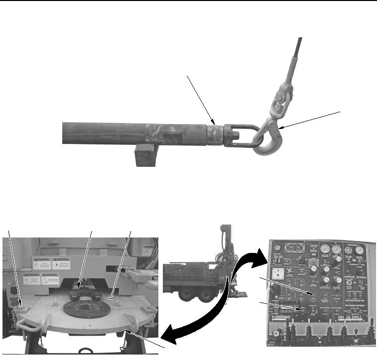
DRILL BIT INSTALLATION - Continued
1
2
WWDS00669
Figure 6.
Hoist Plug to Jib Hook Installation.
9.
Set FORK switch (Figure 7, Item 5) to up position to retract fork (Figure 7, Item 2).
1
2
3
4
5
6
WWDS00670
Figure 7.
Fork Retraction.
10.
Set TABLE switch (Figure 7, Item 4) to up position and retract inner table (Figure 7, Item 3) slightly.
11.
Remove pin (Figure 7, Item 1) from outer table (Figure 7, Item 6).