
TM 5-3820-276-10-1
0027
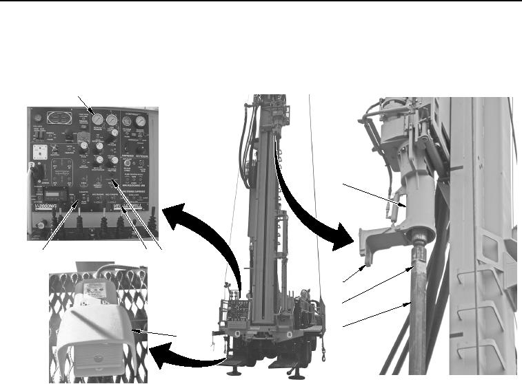
DRILL ROD INSTALLATION - Continued
6.
Set TOP SLIDE switch (Figure 3, Item 7) to right position to position tophead (Figure 3, Item 2) over drill rod
(Figure 3, Item 5).
1
2
7
9
8
3
4
5
6
WWDS00142
Figure 3.
Tophead Mounted Wrench.
7.
Pull ROTATION control lever (Figure 3, Item 9) back slightly to begin rotation of tophead (Figure 3, Item 2).
8.
Pull SLOW FEED control lever (Figure 3, Item 8) back gently to lower tophead (Figure 3, Item 2) until it
enters into female opening of drill rod (Figure 3, Item 5) and is fully seated.
9.
Pull ROTATION control lever (Figure 3, Item 9) back to align tooling joint (Figure 3, Item 4) with tophead-
mounted wrench (Figure 3, Item 3).
NOTE
Ensure TOP SLIDE switch is in right position.
10.
Push foot switch (Figure 3, Item 6) with foot to engage tophead mounted wrench (Figure 3, Item 3).