
TM 5-3820-276-10-1
0025
ARHS OPERATION - Continued
1
4
2
3
WWDS00653
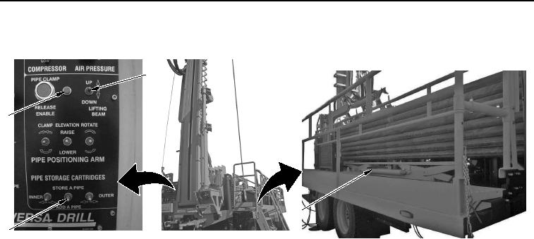
Figure 8.
Lifting Beam.
21.
Set LIFTING BEAM switch (Figure 8, Item 1) to DOWN until lifting beam position indicator light
(Figure 8, Item 4) goes out.
CAUTION
Automated rod handling procedure may need to be stopped and reset. Reset automated
rod handling procedure by placing STORE A PIPE/ADD A PIPE switch momentarily in up
position. Failure to comply may result in damage to equipment.
NOTE
Tophead must be in center of derrick on-hole for any automated functions to work.
Make sure clamps are in open position before lowering automated drill rod
handling arm.
22.
Set STORE A PIPE/ADD A PIPE switch (Figure 8, Item 3) to ADD A PIPE to begin automated rod handling
adding of drill rods.
END OF TASK