
TM 5-3820-276-10-1
0024
MANUAL STORING OF DRILL ROD - Continued
WARNING
Make sure drill rod threaded end is high enough and will not contact base of automated rod
handling arm. Failure to comply may result in injury or death to personnel. Seek medical
attention in the event of an injury.
9.
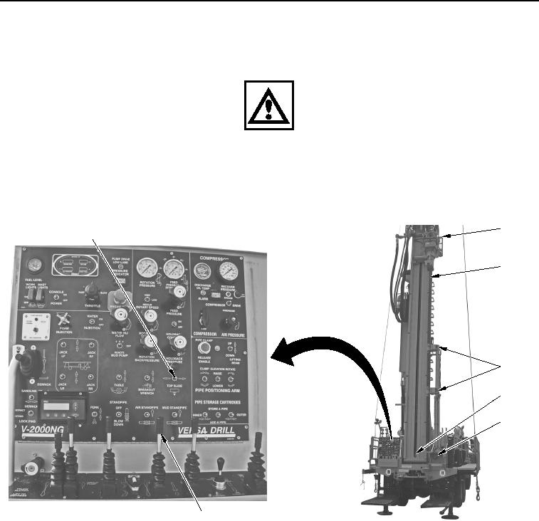
Set TOP SLIDE switch (Figure 15, Item 1) to right position to move tophead (Figure 15, Item 2) and drill rod
(Figure 15, Item 3) until drill rod is positioned in clamps (Figure 15, Item 4).
2
1
3
4
5
6
7
WWDS01047
Figure 15. Tophead Slide Switch.
10.
Push FAST FEED control (Figure 15, Item 7) forward to raise upper drill rod (Figure 15, Item 3) up until
threads (Figure 15, Item 5) are approximately 1 in. (25 mm) above base of automated rod handling arm
(Figure 15, Item 6).
02/13/2013root(opusualwp)wpno(O10010)