
TM 5-3820-276-10-1
0024
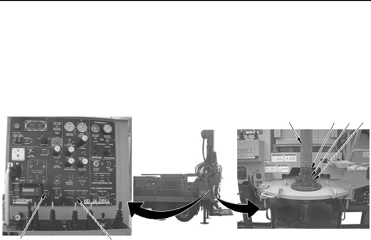
MANUAL STORING OF DRILL ROD - Continued
3.
Push FAST FEED control (Figure 12, Item 5) forward to raise upper drill rod (Figure 12, Item 1) up until top
of tooling joint (Figure 12, Item 3) of lower drill rod (Figure 12, Item 2) is approximately 0.5 in. (13 mm)
above top of fork (Figure 12, Item 4).
1
2
3
4
6
5
WWDS00767
Figure 12. Drill Rod Removal.
4.
Set and hold FORK switch (Figure 12, Item 6) to down position to extend fork (Figure 12, Item 4).
02/13/2013root(opusualwp)wpno(O10010)