
TM 5-3820-276-10-1
0024
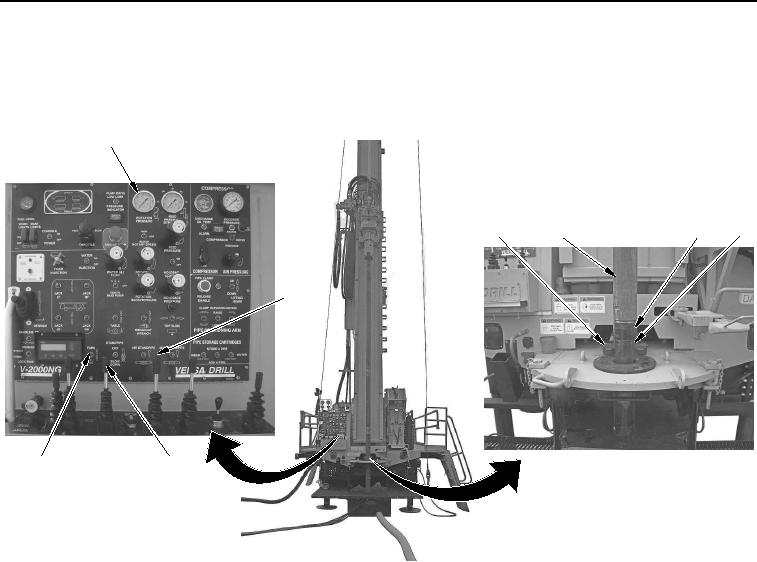
MANUAL OPERATION OF ROD HANDLING SYSTEM - Continued
16.
Pull FAST FEED control (Figure 7, Item 6) back gently to lower upper drill rod (Figure 7, Item 3) until it
enters into female opening of lower drill rod (Figure 7, Item 4).
1
2
4
3
5
6
8
7
WWDS00766
Figure 7.
Drill Rod Attachment.
17.
Pull ROTATION control (Figure 7, Item 7) back slightly to begin rotation of upper drill rod (Figure 7, Item 3).
18.
Pull ROTATION control (Figure 7, Item 7) back to attach upper drill rod (Figure 7, Item 3) to lower drill rod
(Figure 7, Item 4) until ROTATION PRESSURE gauge (Figure 7, Item 1) reads 2,100 psi (145 bar).
19.
Set FORK switch (Figure 7, Item 8) up to retract fork (Figure 7, Item 2) from tooling joint (Figure 7, Item 5).