
TM 5-3820-276-10-1
0024
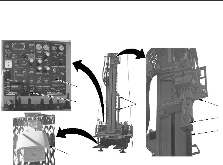
MANUAL STORING OF DRILL ROD - Continued
11.
Pull ROTATION control (Figure 16, Item 5) back to align drill rod tooling joint (Figure 16, Item 3) with
tophead mounted wrench (Figure 16, Item 2).
6
5
7
1
2
3
4
WWDS01048
Figure 16. Tophead Mounted Wrench Foot Switch.
12.
Set and hold PIPE POSITIONING ARM CLAMP switch (Figure 16, Item 6) to up position to close clamps
(Figure 16, Item 7) on drill rod (Figure 16, Item 3).
13.
Push foot switch (Figure 16, Item 4) with foot to engage tophead mounted wrench (Figure 16, Item 2) on drill
rod (Figure 16, Item 3).
14.
Push ROTATION control (Figure 16, Item 5) forward to break joint from tophead (Figure 16, Item 1) to drill
rod (Figure 16, Item 3).
15.
Disengage tophead mounted wrench (Figure 16, Item 2) from drill rod (Figure 16, Item 3) by removing foot
from foot switch (Figure 16, Item 4).
02/13/2013root(opusualwp)wpno(O10010)