TM 10-4930-236-13&P
(4)
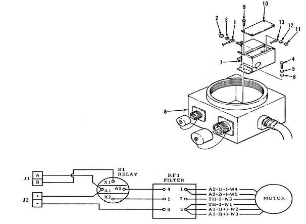
Move the RF1 filter (7) toward the center of opening in junction box (8), then remove screws (9)
and cover (10).
(5)
Make sure the leads from motor are marked as in wiring diagram, then remove nuts (11), star
washers (12) and six motor leads (13). Remove the RF1 filter (7).
c.
Testing RF1 Filter. Test the RF1 filter for continuity across terminals 4-1; 5-2; and 6-3. If there is not
continuity at all three points, the RF1 filter is defective.
d.
Installation of the RF1 Filter.
(1)
Remove screws (9) and cover (10), and position RF1 filter (7) in the junction box (8).
CAUTION
Do not over-tighten nuts. Equipment damage can result from over-tightening.
(2)
Put the six motor leads (13) through the hole in back of RF1 filter and connect to terminals with
star washers (12) and nuts (11). (Refer to wiring diagram for connections.)
(3)
Install cover (10) and screws (9), then move RF1 filter (7) into position with mounting holes
alined. Install flat washer (6), lockwashers (5) and screws (4).
(4)
Connect three leads (1) with star washers (3) and nuts (2).
(5)
Refer to paragraph a. above and install K1 relay.
4-29