TM 5-4320-300-14
5-13.
FUEL CONTROL TUBE ASSEMBLY (CONT)
Location/Item
Action
Remarks
INSTALLATION
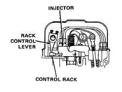
11. Fuel control tube
Engage the rack control levers with control
racks and place brackets over mounting
holes on cylinder head. Install attaching bolts
and lockwashers at each bracket. Torque
bolts to 10 to 12 ft lb (14 to 16 Nm). Check
for freeness in the brackets. Tap control tube
lightly to aline bearings in the bracket, if
necessary.
ADJUSTMENT
WARNING
Exposure to exhaust gases produces symptoms of headache, dizziness, loss of muscular control,
drowsiness, or coma. Brain damage or death can result from severe exposure.
Fumes from engines become concentrated with poor ventilation.
Operate engine in a ventilated area only.
Do not start the engine if rack control levers cannot be placed in the no-fuel position. The loss of
shutdown control could result in a runaway engine, causing personal injury.
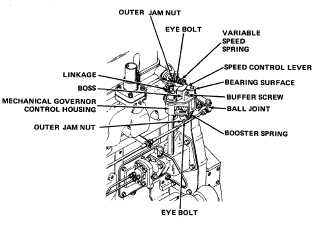
12. Mechanical
governor
Clean and lubricate linkages,
ball joints, and bearing surfaces.
Back out buffer screw until it
projects 9/16 inch (14.3 mm)
from the boss on the control
housing. Back out booster spring
eye bolt until flush with the outer
jam nut.
5-42