TM 5-4320-300-14
5-5. ALTERNATOR ASSEMBLY (CONT)
Location/Item
Action
Remarks
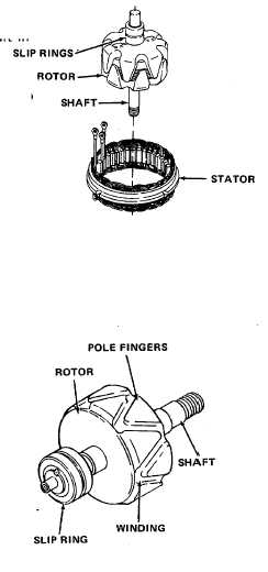
8. Stator and
Inspect for gouged or discolored windings. Dis-
rotor
coloration of winding insulation indicates an
overheated stator or rotor that may result in
shorted or grounded windings.
9. Rotor slip
Inspect for cracks, wear grooves, or other
rings
damage. You can restore a smooth surface to
the slip rings with fine crocus cloth (Federal
Specification P-C-458). Wipe all residue from
slip rings.
10. Rotor shaft
Inspect shaft for stripped threads, cracks, wear,
and body
or other damage. Inspect body for cracked or
marred pole fingers. Replace rotor if damaged.
11. All other parts Inspect for cracks, distortion, or damaged
threads. Replace damaged parts.
TEST
12. Rotor
Set multimeter to resistance scale,
touch probes together, and adjust
OHMS ADJUST for zero resistance.
Place a probe on each slip ring. A
reading of zero resistance indicates
a short circuit in rotor winding. If
winding has a short circuit, replace
rotor. A reading of infinite resist-
ance indicates an open circuit in
rotor winding. If winding has an
open circuit, replace rotor. Place
one test probe on one of the slip
rings and the other probe on a
rotor pole finger. The multimeter
should indicate infinite resistance.
If anything less than infinite re-
sistance is indicated, replace rotor.
13. Bridge recti-
Test the diodes with a multimeter.
fier diodes
5-11