TM 5-4320-300-14
5-5. ALTERNATOR ASSEMBLY (CONT)
Location/Item
Action
Remarks
CAUTION
Equipment damage may occur if acid core solder is used to solder diodes to stator leads. Use
only rosin core solder (ASTM Specification B 284-79).
NOTE
To test, it will be necessary to unsolder the leads from stems of positive and negative diode
assemblies for individual testing. When you solder and unsolder leads from the diodes, use long
nose pliers to grasp diode stem between the diode and stator lead to be removed. This will give
better heat dissipation and protect diode from damage. Make note of diode to stator lead
connections to facilitate reassembly. If one diode is bad, replace entire diode assembly. The
positive diode assembly has red printing on the diode body; the negative diode assembly has
black printing.
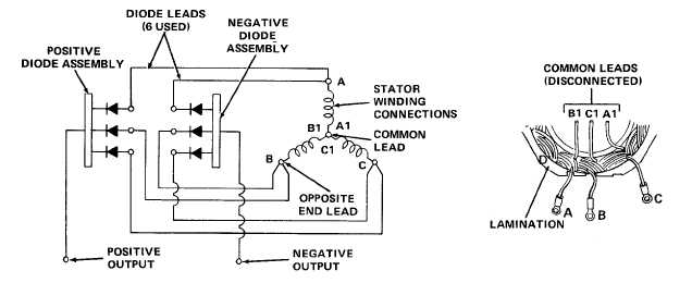
14. Stator
Disconnect stator winding terminals from diode
windings
assemblies, and test stator windings for leakage
and continuity. Set multimeter to read resistance
on the X1 scale. Connect multimeter leads to
each pair of the following test points.
Point A to point B
Point A to point C
Point B to point C
Point A to point D
Point B to point D
Point C to point D
The resistance should be infinite in all of the
above tests. If the resistance reading is not
infinite in any test, high leakage or a short
exists between stator windings, or between a
5-12