
(b) Position a connecting rod in its
piston. Install the piston pin; secure
with the retaining rings (15).
(5)
Slide the piston rings (10, 11, and 12)
squarely into the cylinders in which they
will be used. Check the ring gap with
feeler stock. Ring gap must be within the
following tolerances:
Top ring............... .008 in. to 0.013 in.
0
Middle rings.........0.011 in. to 0.016 in.
Bottom ring..........0.010 in. to 0.020 in.
(6)
If the gap is too small, file the rings to
provide a proper gap.
(7)
Install the piston rings on the piston with a
standard ring expander.
(8)
Assemble
the
remaining
pistons,
connecting rods, and piston rings.
(9)
Install the assembled pistons and connec-
ting rods in the block using a ring
compressor to compress the piston rings.
Lubricate the pistons and cylinder walls
with engine oil before installing the
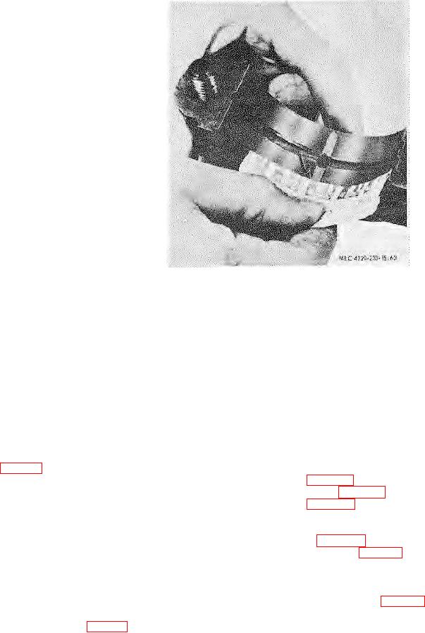
Figure 69. Checking bearing clearance using
pistons. Wrap the bottom end of the
plastigage.
connecting rods with a cloth to prevent
definite drag will be felt. If clearance is
damage to the cylinder walls during
not within tolerance, replace the
installation.
connecting rod bearings and recheck the
(10)
Check the crank pin bearing journal-to-
clearance. If clearance is still not within
connecting rod bearing clearance with
tolerance, replace the crankshaft.
plastigage as follows:
(12) Lubricate the crank pin bearing journals
(a) Place a piece of plastigage near the
and the sleeve bearings with engine oil.
oil hole of the bearing cap.
Install a cap (17) on its connecting rod
(b) Position the cap on the connecting
and on the crank pin bearing journal;
rod and secure with the two nuts
secure with the two bolts (18) and nuts
and lockwashers. Tighten the nuts
(32).
Tighten the nuts to 70 to 75
(32) to 70 to 75 foot ounds torque.
-p
foot-pounds torque. Install the cotter pins
(c) Remove the bearing and bearing
(33).
cap.
Check
the
bearing
(13) Secure the remaining connecting rods to
journal-to-bearing clearance using
the crank pins bearing journals.
plastigage (fig. 63). If clearance is
(14) Install the oil pan (para 117
c).
not between 0.0007 and 0.0025
(15) Install the cylinder head (para 115
c).
inch, replace the connecting rod
(16) Install the engine (para 114
c).
bearings and recheck the clearance.
120. Flywheel and Flywheel Housing
If clearance is still not within
a. Removal.
tolerance, replace the crankshaft.
(1) Remove the engine (para 114).
b
(11)
As an alternate method of checking crank
(2) Remove the six nuts (1, fig. 68) and
pin bearing journalto-connecting rod
-
lockwashers (2) that secure the flywheel
bearing clearance, install a piece of
(3) to the crankshaft (20); remove the
0.0025-inch thick feeler stock between the
flywheel.
bearing and journal.
Lubricate the
(3) Remove the four screws (3, fig. 56),
bearing journal with SAE 10 engine oil.
lockwashers (4), and two nuts (1) that
Install the connecting rod cap. Tighten
secure the flywheel housing (6) to the
the connecting rod cap nuts (32, fig. 68)
block (28); remove the flywheel housing.
to 70 to 75 footpounds torque. Try to
-
slide the connecting rod alternately toward
the front and rear of the engine.
If
clearance is within tolerance, a
TAGO 8368 A
-
80