
(3) Check the fit of the idler gear (26) and the
stud (25); press the stud from the pump
body and press in a new stud if the old
one is worn, or if the idler gear has been
rubbing the walls of the chamber.
(4) Examine the screen for enlarged
openings, breaks, or blocked openings;
clean screen openings or replace.
d. Assembly.
Figure 65. Installing neoprene seal in front filer
(1) Position the key (35, fig. 59) in the slot in
block.
the drive shaft (36). Press the driver gear
(34) on the drive shaft far enough to
lockwashers (63). Tighten the screws to
install the retaining ring (33), install the
12 to 16 footpounds torque.
-
retaining ring and press the gear back
(7) Install the engine (pare 114c).
against the ring.
118. Oil Pump
(2) Place the idler gear (26) in position in the
a. Removal (fig. 59).
pump body (37) and on the stud (25).
(1) Remove the engine (para 114).
b
(3) Install the assembled driver gear and
shaft in the pump body. Press the drive
(2) Remove the oil pan (para 117).
a
gear (40) onto the drive shaft, with the pin
hole the gear in line with the pin hole in
(3) Remove the nut (24) and lockwasher (23)
the shaft; install the pin (39) through the
that secure the oil pump to the center
gear and shaft.
bearing cap; remove the oil pump.
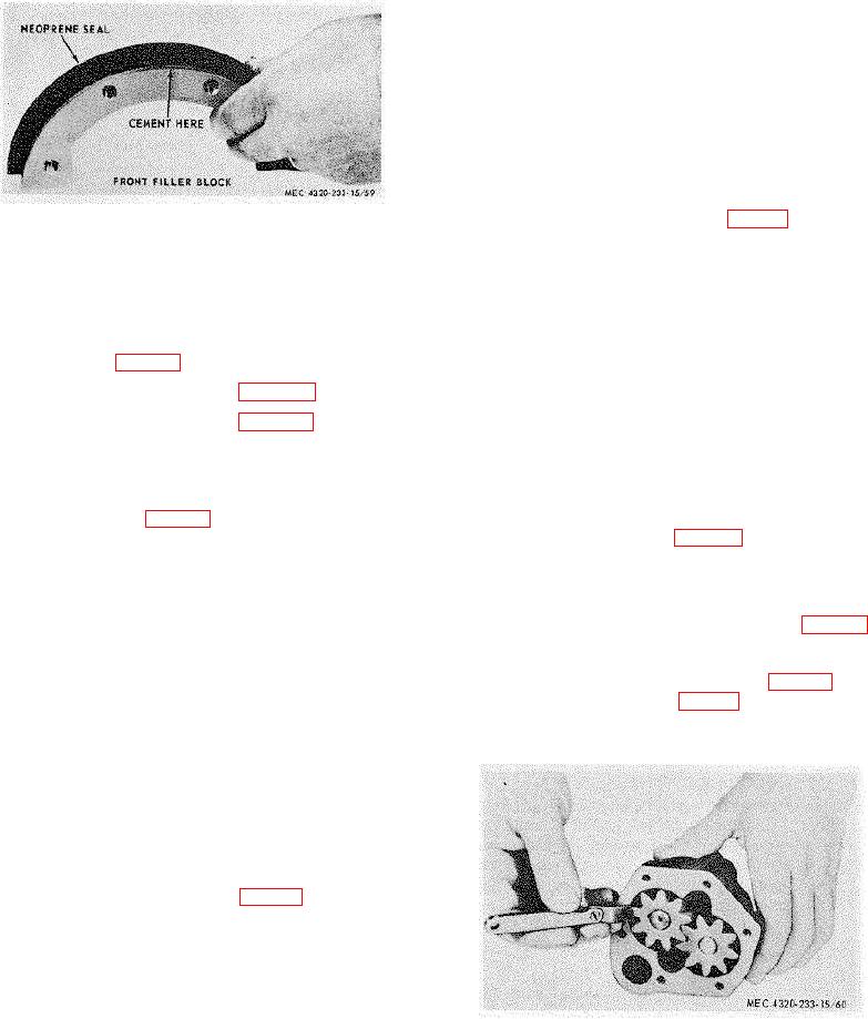
(4) Check the clearance of the gears in the
b. Disassembly (fig. 59).
pump body (fig. 66); there should be
(1) Remove the cotter pin (28) that secures
0.001 to 0.003inch clearance in the
-
the float assembly (27) to the oil pump
chamber. The gears should not contact
cover (31); remove the float.
the chamber walls.
(2) Remove the screws (29) and lockwashers
(5) W ith the cover gasket (32, fig. 59) in
(30) that secure the cover (31) to the
place on the body, there should be
body; remove the cover, gasket (32), and
0.0015- to 0.006 inch clearance between
-
idler gear (26).
the gears and the cover (fig. 67). Install
the cover (31, fig. 59).
(3) Remove the pin (39) that secures the
drive gear (40) to the drive shaft (36);
(6) Install the float assembly (27) on the
remove the gear from the shaft. Remove
pump body.
the assembled driver gear (34) and drive
shaft from the pump body.
(4) Remove the retaining ring (33) from the
lower end of the drive shaft; remove the
driver gear and key (35) from the drive
shaft.
c. Cleaning and Inspection (fig. 59).
(1) Thoroughly clean all parts with an
approved cleaning solvent; dry with clean,
dry, compressed air.
(2) Check the fit of the drive shaft (36) in the
bearing (38) in the top of the oil pump
Figure 66. Checking oil pump gear clearance.
body (37) and in the bearing (41) in the
press in new parts if the old ones are
loose or worn.
TAGO 6358-A
77