
TM 5-4320-218-15
a. Install a battery-powered radio receiver in
wiring and units causing interference. This
good operating condition not more than 10 feet,
shielding does not reduce the intensity of the
from the pump. A wide band receiver cov-
interfering surges, but prevents broadcasting.
ering the frequency ragnge of 0.55 to 156.0
Woven metal conduit is used where flexibility
megacycles is preferred.
is required, while solid conduit is used else-
where.
b. Start the equipment and turn on the re-
ceiver. Turn the receiver volume to maximum
49. Effects of Suppression
and select three widely separated frequencies
There is no interference from equipment sat-
for listening. Use frequencies that are free
isfactorily suppressed for broadcasted interfer-
from signals with strong carriers so that the
ence over the frequency range of 0.55 through
receiver will be in its most sensitive operating
156.0 50. megacycles at a distance of 25 feet
condition.
from the unit.
c. Systematically replace suppression compo-
50. Suppression System Testing
nents in the circuit causing trouble, testing af-
ter the replacement of each component to see if
This testing is performed by 3d echelon or
the trouble has been eliminated.
higher.
Section VI. ENGINE FUEL SYSTEM
51. Description
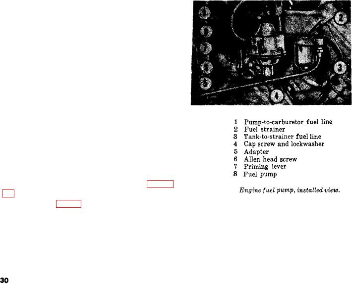
The engine fuel system consists of a fuel
tank, fuel pump, fuel strainer, fuel-pump adapt-
er, and hand primer, carburetor, governor, air
cleaner, and fuel lines and connections. Fuel is
drawn from the tank to the strainer, which re-
moves solids and water from the fuel. The
strained fuel passes through the fuel pump and
into the carburetor. The oil-bath air cleaner re-
moves any dust, water, or foreign matter from
the air, and passes clean air to the carburetor
to be mixed with the fuel for proper combus-
tion.
52. Air Cleaner
a. General. The air cleaner is of the oil-bath
type. Air enters the cleaner through the top,
then passes over the oil in the cup and through
the body screen, where any solids or water pres-
ent are left behind. The filtered air then passes
through the air pipe to the carburetor, Figure
Figure 9.
10 shows an exploded view of the air cleaner.
b. Removal (fig. 10),
move the hose (4) from the air
(1) Loosen the screw in the hose clamp (1)
cleaner.
at the carburetor; remove the elbow
(3) Remove the four cap screws (12), lock-
(2) from the carburetor and lift off
washers (11), and hex nuts (10) se-
the spacer,
curing the mounting strap (13) to the
(2) Loosen the screw in the hose clamp
front engine panel; remove the assem-
(1) at the air-cleaner body (6); re-
bled air cleaner and mounting bracket.