
TM 5-3825-270-23&P
0183
INSTALLATION - Continued
1
2
3
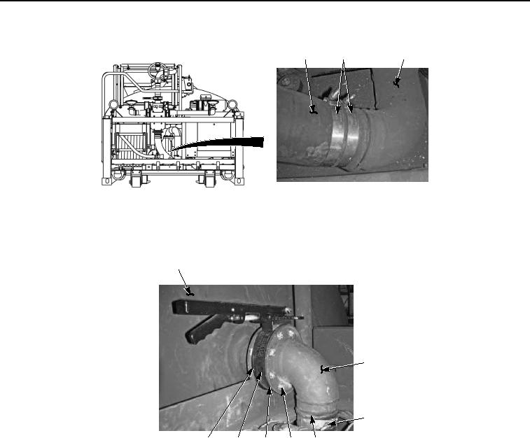
Figure 4. Inlet Valve and Hose Installation.
2.
Install inlet elbow (Figure 5, Item 5) into inlet hose (Figure 5, Item 1) with two clamps (Figure 5, Item 6). Do
not tighten clamps.
4
5
6
11
10
9
7, 8
1
Figure 5. Inlet Valve and Hose Installation.
3.
Install inlet elbow (Figure 5 Item 5), gasket (Figure 5, Item 11), inlet valve (Figure 5, Item 10), and gasket
(Figure 5, Item 9) on tank (Figure 5, Item 4) with eight screws (Figure 5, Item 8) and locknuts (Figure 5, Item
7).
4.
Install two clamps (Figure 5, Item 6) onto inlet hose (Figure 5, Item 1) and inlet valve (Figure 5, Item 5). Tighten
two clamps to 70 lb-in (8 Nm).
5.
Install two clamps (Figure 6, Item 2) onto inlet hose (Figure 6, Item 1) and discharge tube (Figure 6, Item 3).
Tighten two clamps to 70 lb-in (8 Nm).