
TM 5-3825-270-23&P
0171
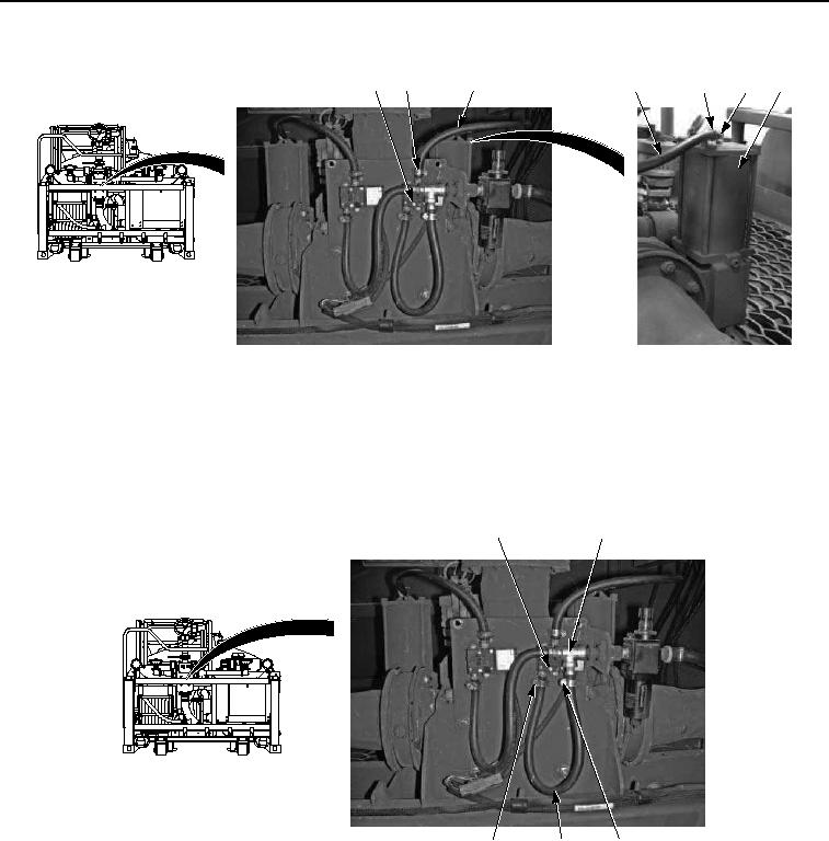
INSTALLATION - Continued
16
15
11
16
17
18
19
Figure 5. Air Hose Installation.
2.
Install fitting (Figure 5, Item 18) on air actuator (Figure 5, Item 19).
3.
Install hose (Figure 5, Item 16) on fitting (Figure 5, Item 18) with clamp (Figure 5, Item 17).
4.
Install hose (Figure 5, Item 16) on solenoid valve (Figure 5, Item 11) with clamp (Figure 5, Item 15).
5.
Install hose (Figure 6, Item 13) on solenoid valve (Figure 6, Item 11) with clamp (Figure 6, Item 14).
11
3
14
13
12
Figure 6. Air Hose Installation.
6.
Install hose (Figure 6, Item 13) on fitting (Figure 6, Item 3) with clamp (Figure 6, Item 12).