
TM 5-3825-270-23&P
FIELD MAINTENANCE
ROLLER REPAIR
INITIAL SETUP:
Materials/Parts (cont.)
Tools and Special Tools
Cleaning Compound, Solvent (WP 0224, Table 1,
Compressor Unit, Air (WP 0225, Table 1, Item 2)
Item 10, 11, 12, 13, 14, 15)
Gloves, Rubber (WP 0225, Table 1, Item 2)
Pin, Cotter (WP 0226, Table 1, Item 15) Qty: 1
Goggles, Industrial (WP 0225, Table 1, Item 12)
Gun, Air Blow (WP 0225, Table 1, Item 2)
Tool Kit, General Mechanic's: Automotive
References
(WP 0225, Table 1, Item 12)
Parts Manual (WP 0220) Figure 4003
Materials/Parts
Equipment Condition
Cloth, Cleaning, Low-Lint (WP 0224, Table 1, Item
Roller removed. (TM 5-3825-270-10)
16, 17)
DISASSEMBLY
NOTE
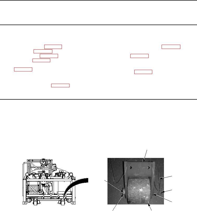
Both left and right rollers are repaired the same way. Right side shown.
Note and tag location of roll pin and collar prior to removal to ensure proper installation.
1.
Remove cotter pin (Figure 1, Item 1) from collar (Figure 1, Item 7). Discard cotter pin.
2
3
1
4
5
7
6
Figure 1. Roller Disassembly.
2.
Remove collar (Figure 1, Item 7), roller shaft (Figure 1, Item 5), and roller (Figure 1, Item 6) from bracket (Figure
1, Item 2).
NOTE
Perform Step (3) if retaining pins are damaged.