
TM 5-3825-270-23&P
FIELD MAINTENANCE
EXHAUST FLEX PIPE REPLACEMENT
INITIAL SETUP:
Tools and Special Tools
Materials/Parts (cont.)
Tool Kit, General Mechanic's: Automotive
Gasket, Manifold (WP 0226, Table 1, Item 17)
(WP 0225, Table 1, Item 12)
Qty: 1
Stud (WP 0226, Table 1, Item 1) Qty: 4
Materials/Parts
References
Antiseize Compound (WP 0224, Table 1, Item 4)
Lockwasher (WP 0226, Table 1, Item 3) Qty: 4
Parts Manual (WP 0220) Figure 4025
Parts Manual (WP 0220) Figure 4040
Equipment Condition
Engine compartment cover removed. (WP 0142)
REMOVAL
WARNING
Exhaust pipes and muffler can become very hot during engine operation. Allow parts to cool
and take care not to touch these parts with bare hands or allow body to contact exhaust pipes
or muffler. Failure to comply may result in injury or death to personnel.
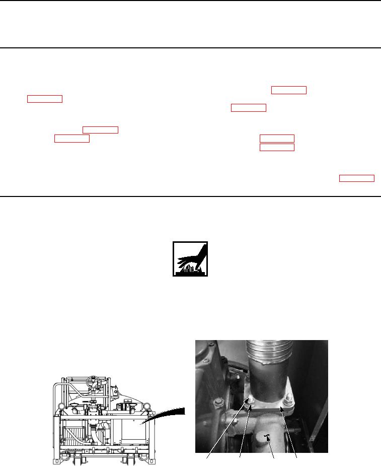
1.
Remove four nuts (Figure 1, Item 4) and lockwashers (Figure 1, Item 5) from exhaust flex pipe (Figure 1, Item
1). Discard lockwashers.
6
4, 5
3
1, 2
Figure 1. Exhaust Flex Pipe Removal.