
TM 5-3825-270-23&P
0091
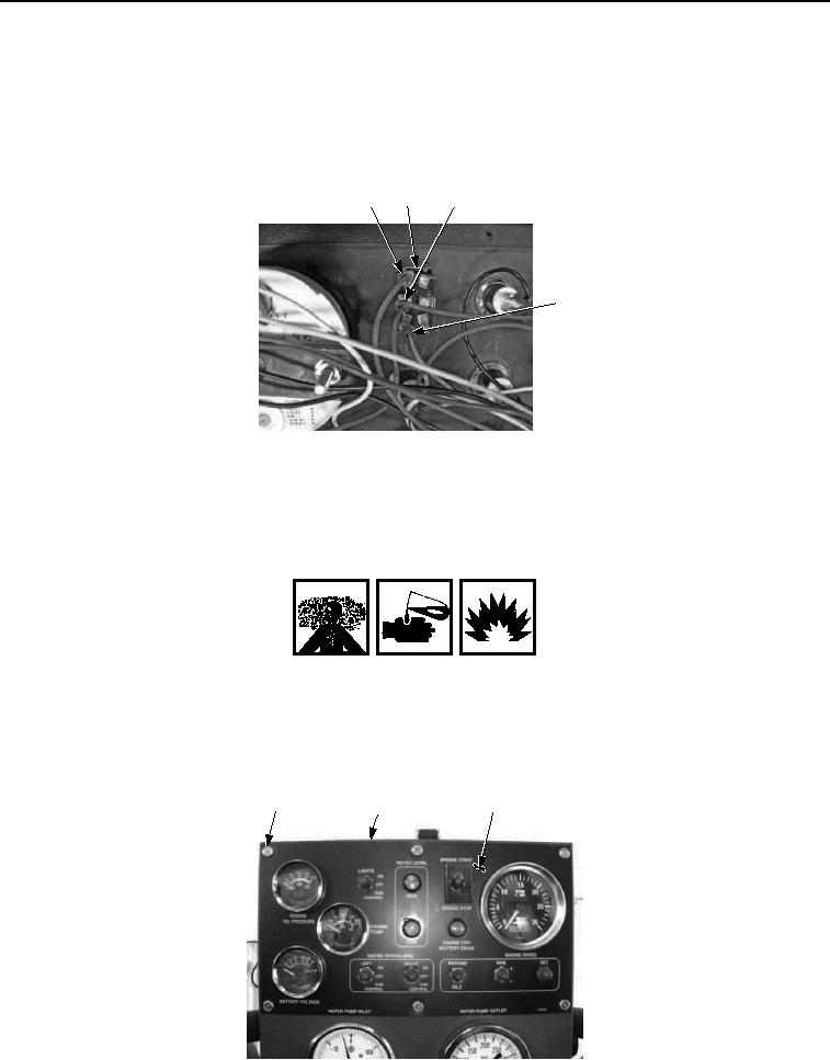
INSTALLATION - Continued
NOTE
Install wires as noted prior to removal.
3.
Install orange wire with black stripe (Figure 6, Item 10) on main control panel engine start/stop switch (Figure
6, Item 8).
7
8
9
10
Figure 6. Main Control Panel Engine Start/Stop Switch Installation.
4.
Install two red wires (Figure 6, Item 9) on main control panel engine start/stop switch (Figure 6, Item 8).
5.
Install orange wire (Figure 6, Item 7) on main control panel engine start/stop switch (Figure 6, Item 8).
WARNING
Adhesives, solvents, and sealing compounds can burn easily, can give off harmful vapors,
and are harmful to skin and clothing. Keep away from open fire and use in well-ventilated
area. If adhesive, solvent, or sealing compound gets on skin or clothing, wash immediately
with soap and water. Failure to comply may result in injury or death to personnel.
6.
Apply sealant to the threads of six screws (Figure 7, Item 3).
5
6
3, 4
Figure 7. Main Control Panel Engine Start/Stop Switch Installation.