
TM 5-3825-270-23&P
0091
REMOVAL - Continued
11
8, 12
6
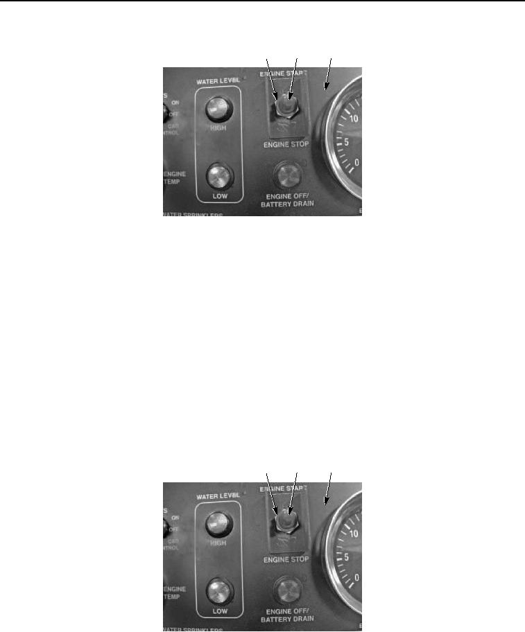
Figure 4. Main Control Panel Engine Start/Stop Switch Removal.
NOTE
Note position of main control panel engine start/stop switch prior to removal to ensure proper
installation.
7.
Remove nut (Figure 4, Item 11) and main control panel engine start/stop switch (Figure 4, Item 8) from control
panel (Figure 4, Item 6).
END OF TASK
INSTALLATION
NOTE
Install main control panel engine start/stop switch as noted prior to removal.
1.
Install main control panel engine start/stop switch (Figure 5, Item 8) on control panel (Figure 5, Item 6) with
nut (Figure 5, Item 11).
11
8, 12
6
Figure 5. Main Control Panel Engine Start/Stop Switch Installation.
2.
Install toggle switch seal (Figure 5, Item 12) on main control panel engine start/stop switch (Figure 5, Item 8).