
TM 5-3820-276-10-1
0062
WWSV WATER TANK FILLING PROCEDURE - Continued
NOTE
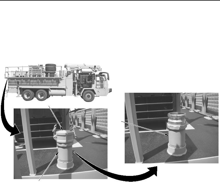
There are two water tank fill caps located on top of the WWSV. One is located at the rear,
on top of the water tank. The other one is located between the spare tire rack and the
grouter, on top of the water tank. Rear fill cap is shown.
3.
Remove water tank fill cap (Figure 2, Item 1) from fill stand pipe (Figure 2, Item 2).
1
2
2
WWDS00915
Figure 2.
Water Tank Fill Cap and Stand Pipe.
4.
Connect suitable water source hose to fill stand pipe (Figure 2, Item 2).