
TM 5-3820-276-10-1
0007
Table 3.
Drill Operator Control Panel - WWDR - Continued.
Key
Control/Indicator
Function
7.
DERRICK LOCK
Used to activate two double-acting air cylinders that pin and unpin the derrick
PINS Switch
to drill deck.
8.
SANDLINE JIB
Used to operate jib on operators side of derrick.
Switch
9.
DERRICK Control
Used to raise and lower derrick.
Joystick
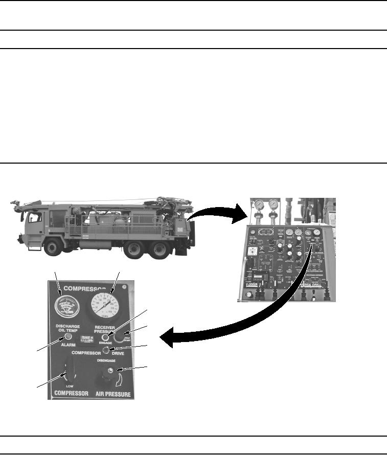
Table 4.
Drill Operator Control Panel - WWDR.
1
2
3
4
5
8
6
7
WWDS00073
Figure 4.
Drill Operator Control Panel (View 4) - WWDR.
Key
Control/Indicator
Function
1.
DISCHARGE OIL
Displays the temperature of the oil at the discharge of the air compressor.
TEMP Gauge