
TM 5-3820-276-10-1
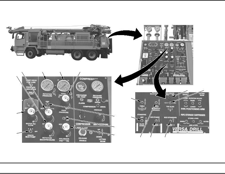
0007
Table 2.
Drill Operator Control Panel - WWDR.
5
2
3
4
1
7
8
6
17
13
12
14
16
15
11
10
9
WWDS00071
Figure 2.
Drill Operator Control Panel (View 2) - WWDR.
Key
Control/Indicator
Function
1.
ROTATION
Used to increase back pressure to reduce jerking or cogging in drill string.
BACKPRESSURE
Regulator
2.
ROTATION
TORQUE Regulator
3.
ROTATION
Displays the system pressure in the working side of the circuit.
PRESSURE Gauge
4.
FEED PRESSURE/
Displays the pressure being exerted in the feed cylinder.
STRING WT.
Gauge
5.
FEED PRESSURE
Regulates the pressure produced when the slow drill feed selector is
Regulator
engaged.