
TM 5-3820-276-10-1
0007
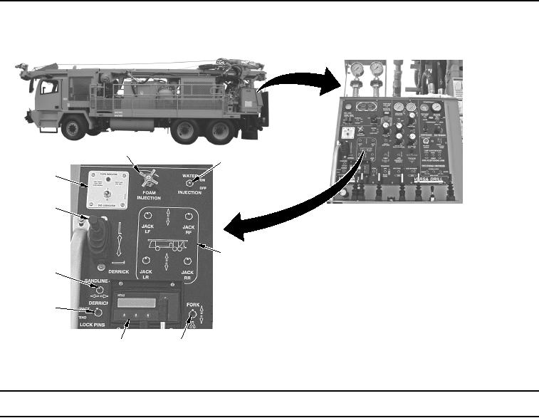
Table 3.
Drill Operator Control Panel - WWDR.
2
3
1
9
4
8
7
6
5
WWDS00072
Figure 3.
Drill Operator Control Panel (View 3) - WWDR.
Key
Control/Indicator
Function
1.
DHD
Used to operate the Down-Hole-Drill (DHD) oiler when the compressor is
LUBRICATOR/
running. Green indicator light will flash when oiler is in operation.
FLOW INDICATOR
2.
FOAM INJECTION
Regulates the amount of foam added to water injection.
Regulator
3.
WATER
Used to turn water injection pump ON or OFF.
INJECTION Switch
4.
Leveling JACK
Used to level vehicle. There are two switches for front jacks and two
Switches
switches for rear jacks.
5.
FORK Switch
Used to position lower holding wrench.
6.
IQAN Display
Displays engine information and automation functions.