
TM 5-3820-276-10-1
OPERATOR MAINTENANCE
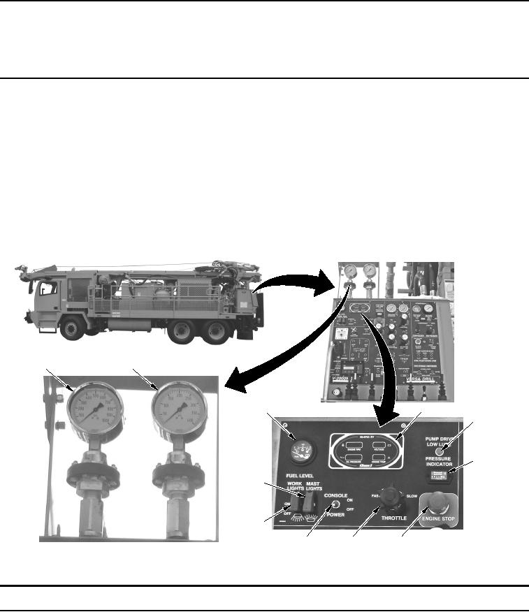
DESCRIPTION AND USE OF CONTROLS AND INDICATORS - WATER WELL DRILLING RIG (WWDR) AND
WATER WELL SUPPORT VEHICLE (WWSV) REAR CONTROL PANELS
INTRODUCTION
NOTE
Before attempting to operate the WWDR or WWSV, be familiar with location and
function of all controls and indicators.
Illustrations shown with console cover panel removed from WWDR and rear work
platforms lowered on WWDR and WWSV.
This Work Package provides the description and use of WWDR and WWSV rear control panels.
Table 1.
Drill Operator Control Panel - WWDR.
1
2
3
4
5
6
11
10
9
8
7
WWDS00070
Figure 1.
Drill Operator Control Panel (View 1) - WWDR.
Key
Control/Indicator
Function
1.
Pressure Gauge
Displays mud pressure in standpipe.
2.
Pressure Gauge
Displays air pressure in standpipe.