TM 10-4320-344-24
4.4.14 Piston and Connecting Rod Assembly Maintenance, Model 609-A. (Continued)
4.4.14.5 Installation.
Cylinder number is stamped on connecting rods and caps on front,
camshaft-side of engine.
a .
Select proper piston and connecting rod assembly for first cylinder bore.
b .
Turn crankshaft so connecting rod journal for number 1 cylinder is at BDC.
c .
Coat cylinder bores, piston (10), rings (4, 5, 6, and 7), piston pin (9), and
crankshaft journal with lubricating oil.
Piston is inserted from top of cylinder block.
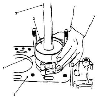
Figure 4-22. Piston and Connecting Rod Assembly Installation, Model 609-A.
d .
Using ring compressor (Figure 4-21, 1), compress piston rings to help in
installation of piston and rod assemblies (2).
When installing piston, make sure connecting rod is in line with, and will
not score crankshaft journal.
e.
Place hammer handle (3) against top of piston and rod assembly (2) and push
piston into cylinder bore in engine block (4). Remove ring compressor (1).
f .
With piston and rod assembly (2) entirely in cylinder bore in engine block
(4), insert upper bearing (Figure 4-19, 13) in connecting rod (12).
g.
Pull piston and rod assembly (Figure 4-21, 2) down until upper rod bearing
Figure 4-18, 13) seats firmly on crankshaft journal.
4-48
NOTE
NOTE